
What is Metastability and MTBF in the context of clock domain crossing

Title Image: I asked chatgpt to create an image showing metastability and it made this. It makes no sense but looks so cool so I thanked it and put it here :)
What is Metastability?
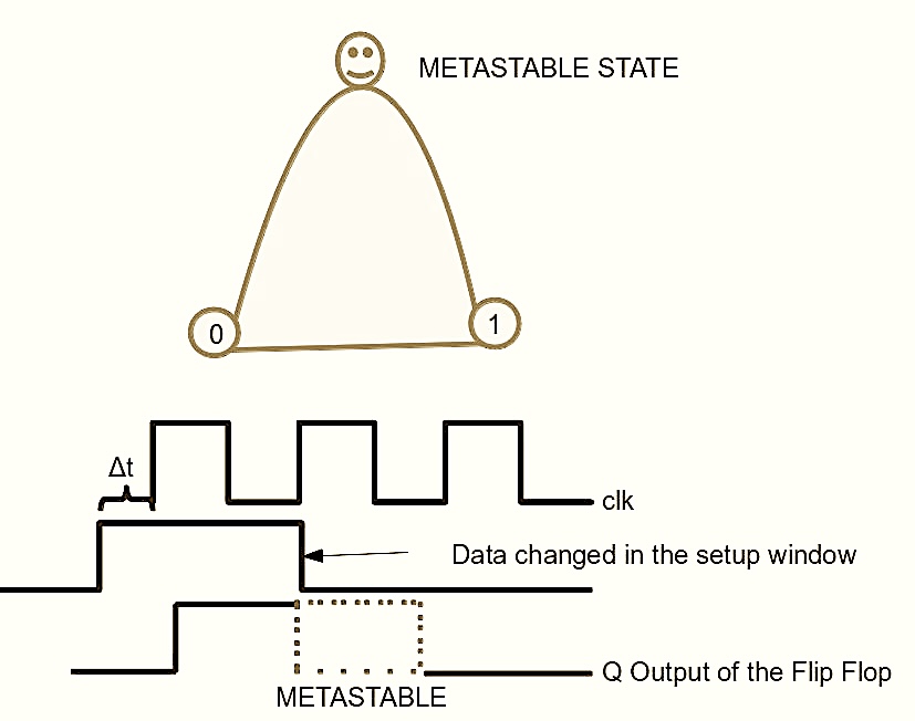
Metastability is the unpredictable behaviour that occurs at the output of a flip flop or a latch where its output assumes unspecific values between 0 and 1 for unspecific periods of time.
In the context of a flip flop, metastability is seen when it’s input changes too close to its setup and hold windows, where the input is supposed to be held stable.
Now, if that makes you wonder what exactly are setup and hold windows, or perhaps even ‘why do these windows exist?’ You should read this well written article and come back.
Does metastability mean failure?
To answer this, we need to define what failure exactly means in the context of our system. Metastability happens everywhere, when we type too fast on the keyboard and end up misspelling something because we didn’t press a key properly or long enough, that’s metastability. But does that have to mean our system fails completely and has to be thrown away? Well if that’s the case, it could be a badly designed system. Because metastability cannot be ‘solved’ with a 100% guarantee. It can only be isolated and minimised to a statistically reasonable extent.
Any system, no matter how well designed will see metastability happening at some point of time even if that time is a 100 million years.
Hence, a well designed system also has redundancy and intelligence in the outer loops (like software that controls your hardware) to detect these events , reset the system and bring it back up.
There is one case though in which metastability can literally ‘burn’ the chip due to excessive current flow. Let’s say you let the output of the first synchroniser flop pass into a large combination cloud and at some point the metastability at the output of this flop takes an unusually long time to settle. All of the gates in the combo cloud will be driven into the short circuit region where there is maximum current flowing between Vcc and ground. This can sometimes cause the chip to burn forcing you to throw it away.
How then, do you characterise this phenomenon and sign-off saying that your design is ‘good enough’ for the target application? The MTBF will tell you that.
What MTBF means and why it’s important
MTBF stands for Mean time between Failures. This is a very popular and standard reliability metric in almost every industry that manufactures products and devices.
MTBF is calculated for everything from mechanical tools, medical devices to components that go into satellites.
It is only a probabilistic measure that tells you the average amount of time between two consecutive failures of the system. Ideally we want it to be very large. Like super large. Like the lifetime of the universe.
Here’s how MTBF is defined in the context of a clock domain crossing setup:
- It seems this equation was first put forth in this book. It looks like below:
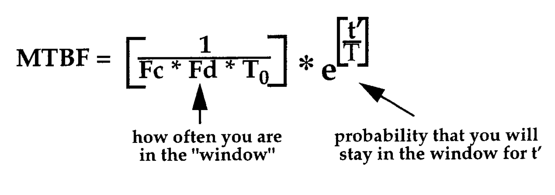
Many papers will term T0 as K1 and 1/T as K2. But they’re all saying the same thing
Here,
Fd ⇒ Frequency of the data. Now this may not be very straight forward for signals like button clicks or resets that are not coming from any clock. We’ll just have to put an equivalent number that captures how frequently this signal can change.
Fc ⇒ Frequency of the clock that’s capturing the asynchronous signal. The destination clock.
T0 and 1/T ⇒ are related to the Gain Bandwidth Product (GBW) of the master latch in the flip flop. The GBW is a figure of merit used to describe characteristics of amplifiers.
In simpler terms, it gives an estimate of how fast the analog electronics acts within the flop. The faster the better. These parameters can also be sensitive to temperature, voltage and process nodes. If you have a choice, simply use the devices with the fastest flops to maximize your MTBF.
t` (or Tau) ⇒ This is another parameter that gives us some ideas on how to improve the MTBF of our circuit. This essentially represents how much time your design afford to let the metastability resolve.
It can be seen that t` = tclk - (tsu + tckq + tpd)
where tclk ⇒ Fc , tsu ⇒ setup time of the destination flop (the flop that follows the synchroniser flop), tckq ⇒ clock to q delay of the source flop (synchroniser flop) and tpd ⇒ the propagation delay through the wire from source to destination.
Plugging in the above parameters, you can get an MTBF number.
This amazing paper by Peter Alfke from Xilinx conducts an experiment to calculate the MTBF of the flops in Virtex-II Pro FPGA. Definitely have a look!
From the above equation is is obvious that the exponential portion, which is controlled by t` (tau) and 1/T or (K2) have the highest impact on the MTBF value. Once a technology is chosen, K2 can no longer be changed. So our focus should be on in increasing t` (tau) as much as possible.
Let’s see how that can be done.
How the classic multi-flop synchroniser maximises MTBF:
The most popular and standard circuit structure that designers use to tackle metastability is the multi-flop synchroniser.
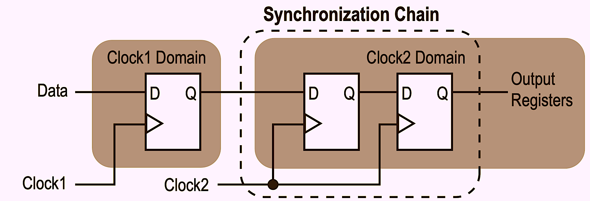
All this is doing is giving the metastable flop (A) a full extra clock cycle to stabilize it’s output and feed a clean logic level to the rest of the circuit.
In applications like space and medical devices, it is mandated by standards to use at least three flops for synchronisation. The price you pay here is the latency. Which may or may not be significant depending on your application.
The MTBF of the multi-flop synchroniser system can be derived from the equation :
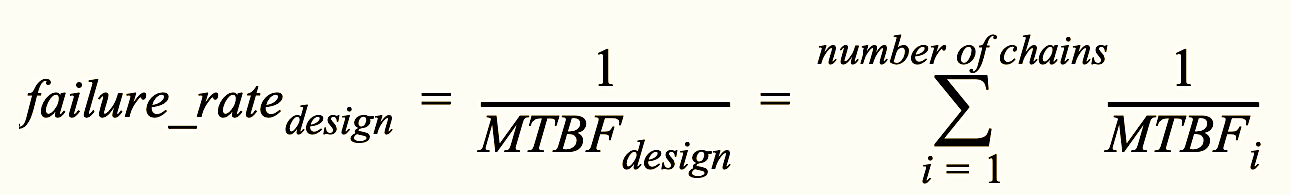
MTBFdesign = 1/(failurerate_design)
Good design practices to maximize MTBF
Place the sync flops very close to each other to minimize Tpd. This maximises t`
One thing you can ensure is that by placing the synchroniser flops A and B physically close to each other, a majority of the clock cycle time is available for the metastability to settle (t` or tau in the above equation) since Tpd (propagation delay) has gone down to almost zero.
In FPGAs you can ensure this by using the ‘async_reg’ attribute (xilinx) that ensures the placer puts these flops very close.
In ASICs there are dedicated library cells for synchronisers that are inferred from the RTL.
Does a synchroniser only safeguard against metastability or does it also guarentee functinal correctness?
This is an important question that throws off many people.
The synchronizer is meant to reduce the probability of a metastable event spreading to the entire circuit. But in the off chance that metastability does occur (which it will, in a long enough time scale) it can settle towards any logic level. transferring the wrong value to the destination domain.
There are several practices and designs that ensure the design does not break when things like this happen. Here’s an exhaustive list of those techniques.
To end, at any point if you have this feeling that you wish to do a Phd on the nature of metastability. Here are wonderful and challenging paper1 and paper2 for you.