
Creating automated testbenches for your digital designs using python and iverilog

Verification is a pain, especially when most of the verification technologies are so involved and there's hardly any good resource available for the same freely on the internet. Every time I design something, I look for a way to throw processing power at my design and try to find corner cases that I'm unable to think of. While this might not be ideal or efficient for large designs that take lots of time to simulate and might not really find bugs for you after a point, it can give you enormous advantage when checking small designs by providing you super-fast feedback about the flaws in you code in the form of failing test cases, especially in the initial stages of your design.
In this article, we're going to take a look at one such quick and dirty method to use your computer's processing power to quickly iterate over your designs and find corner cases that you could not have thought of with a simple manual testbench.
For this article, we shall be testing the MAC (Multiply and Accumulate) Unit that I had to design for this article.
The Simulator
Of course, we'll be needing a simulator to interpret and run the Verilog for us. we can choose any one for this process as long as we know how to operate it in the command line mode. I'm currently using the 'Icarus Verilog' simulator because its opensource and quite fast compared to a lot other proprietary ones.
For help with installing Icarus Verilog, you can use this or this source and you should be good to go.
The Golden Model
The basic idea of an automated testbench is to have a golden model that is proven and always outputs the correct values for a given set of inputs. While the golden model can be built in many ways, my favorite has always been python, given it's ease of use and powerful set of libraries for anything in the domain of mathematical computation. Python makes your life easier especially when your task involves DSP related of algorithmic stuff that lends itself easily to software.
Let's take a look at our python model of a Multiply and Accumulate unit
import numpy as np
import subprocess
import os
import math

#Function to truncate (not round) any floating point number to two decimal places
def truncate(number, digits) -> float:
    stepper = 10.0 ** digits
    return math.trunc(stepper * number) / stepper

NoT = 10 # Number of tests to be run

for i in range(NoT):
    #choosing the values of a,b,c randomly
    a = np.random.uniform(-1,1,1)[0]
    b = np.random.uniform(-1,1,1)[0]
    c = np.random.uniform(-1,1,1)[0]
	#performs the MAC (Multiply and Add) operation
    p_golden = a*b + c
    #truncating to two decimal places because the value generated by our hardware will never be the
    #exact same owing to the precision loss due to fixed point representation.
	p_golden_trunc = truncate(p_golden,2)
The above code is going to generate random floating point data that we can pass on to our Verilog module and compare its results with those of this python code itself. But our design does not understand floating point representation, it is build for a particular fixed-point precision. So to be able to do that, we need to format our data into the representation that our hardware can comprehend. Let's write some code to do that...
#Function to convert values from the exact fixed point precision that our hardware
#is designed to the floating point format that python can use
def fp_to_float(s,integer_precision,fraction_precision):       #s = input binary string
    number = 0.0
    i = integer_precision - 1
    j = 0
    if(s[0] == '1'):
        s_complemented = twos_comp((s[1:]),integer_precision,fraction_precision)
    else:
        s_complemented = s[1:]
    while(j != integer_precision + fraction_precision -1):
        number += int(s_complemented[j])*(2**i)
        i -= 1
        j += 1
    if(s[0] == '1'):
        return (-1)*number
    else:
        return number
#Function to convert floating point values generated by python into the exact
#fixed point precision that our hardware is designed for
def float_to_fp(num,integer_precision,fraction_precision):
    if(num<0):
        sign_bit = 1                                          #sign bit is 1 for negative numbers in 2's complement representation
        num = -1*num
    else:
        sign_bit = 0
    precision = '0'+ str(integer_precision) + 'b'
    integral_part = format(int(num),precision)
    fractional_part_f = num - int(num)
    fractional_part = []
    for i in range(fraction_precision):
        d = fractional_part_f*2
        fractional_part_f = d -int(d)
        fractional_part.append(int(d))
    fraction_string = ''.join(str(e) for e in fractional_part)
    if(sign_bit == 1):
        binary = str(sign_bit) + twos_comp(integral_part + fraction_string,integer_precision,fraction_precision)
    else:
        binary = str(sign_bit) + integral_part+fraction_string
    return str(binary)
#Function to calculate two's complement value of a binary string
def twos_comp(val,integer_precision,fraction_precision):
    flipped = ''.join(str(1-int(x))for x in val)
    length = '0' + str(integer_precision+fraction_precision) + 'b'
    bin_literal = format((int(flipped,2)+1),length)
    return bin_literal
The integer_precision and the fraction_precision arguments in the above code tell the functions how many bits to be allotted to the integral part of the number and how many to the fractional part. This aspect of our Verilog code is also parameterized so that we can test our module with various precision values without having to change the underlying code. To see what I mean by that, let's take a look at the Verilog Code!
The Code
//file: mac_manual.v
//This module simply calculates a*b+c

`define FIXED_POINT 1  //compiler driven macro to select between normal multipliers/adders and fixed                        //point multipliers/adders
module mac_manual #(parameter N = 16,parameter Q = 12)(
    input clk,sclr,ce,
    input [N-1:0] a,
    input [N-1:0] b,
    input [N-1:0] c,
    output [N-1:0] p
    );

`ifdef FIXED_POINT      //This block is only instantiated if FIXED_POINT macro is defined
    wire [N-1:0] mult,add;
    reg [N-1:0] tmp;
    wire ovr;
    //The fixed point multipleir
    qmult #(N,Q) mul (
                .clk(clk),
                .rst(sclr),
                .a(a),
                .b(b),
                .q_result(mult),
                .overflow(ovr)
                );
    //The fixed point adder
    qadd #(N,Q) add1 (
                .a(mult),
                .b(c),
                .c(add)
                );

    always@(posedge clk,posedge sclr)
           begin
               if(sclr)
               begin
                   tmp <= 0;
               end
               else if(ce)
               begin
                   tmp <= add;
               end
           end
           assign p = tmp;
`else                  //The following block is only instantiated if FIXED_POINT is not defined
    reg [N-1:0] temp;
    always@(posedge clk,posedge sclr)
    begin
        if(sclr)
        begin
            temp <= 0;
        end
        else if(ce)
        begin
            temp <= (a*b+c);
        end
    end
    assign p = temp;
 `endif
endmodule
The fixed point multiplier and the Fixed point adder are built as shown below
//file: qmult.v
// (Q,N) = (12,16) => 1 sign-bit + 3 integer-bits + 12 fractional-bits = 16 total-bits
//                    |S|III|FFFFFFFFFFFF|
// The same thing in A(I,F) format would be A(3,12)
module qmult #(
	//Parameterized values
	parameter N = 16,
	parameter Q = 12
	)
	(
	 input                  clk,
	 input                  rst,
	 input			[N-1:0]	a,
	 input			[N-1:0]	b,
	 output         [N-1:0] q_result,    //output quantized to same number of bits as the input
     output			overflow             //signal to indicate output greater than the range of our format
	 );

	 //	The underlying assumption, here, is that both fixed-point values are of the same length (N,Q)
	 //	Because of this, the results will be of length N+N = 2N bits
	 //	This also simplifies the hand-back of results, as the binimal point
	 //	will always be in the same location

	wire [2*N-1:0]	f_result;		//	Multiplication by 2 values of N bits requires a
									//	register that is N+N = 2N deep
	wire [N-1:0]   multiplicand;
	wire [N-1:0]	multiplier;
	wire [N-1:0]    a_2cmp, b_2cmp;
	wire [N-2:0]    quantized_result,quantized_result_2cmp;

	assign a_2cmp = {~a[N-1],~a[N-2:0]+ 1'b1};  //2's complement of a {(N-1){1'b1}} -
	assign b_2cmp = {~b[N-1],~b[N-2:0]+ 1'b1};  //2's complement of b  {(N-1){1'b1}} -

    assign multiplicand = (a[N-1]) ? a_2cmp : a;
    assign multiplier   = (b[N-1]) ? b_2cmp : b;
    //We remove the sign bit for multiplication
    assign f_result = multiplicand[N-2:0] * multiplier[N-2:0];
    //Sign bit of output would be XOR or input sign bits
    assign q_result[N-1] = a[N-1]^b[N-1];
    //Quantization of output to required number of bits
    assign quantized_result = f_result[N-2+Q:Q];
    //2's complement of quantized_result
    assign quantized_result_2cmp = ~quantized_result[N-2:0] + 1'b1;
     //If the result is negative, we return a 2's complement representation of the output value
    assign q_result[N-2:0] = (a[N-1]^b[N-1]) ? quantized_result_2cmp : quantized_result;

    assign overflow = (f_result[2*N-2:N-1+Q] > 0) ? 1'b1 : 1'b0;

endmodule
//file: qadd.v
module qadd #(
parameter N = 16,
parameter Q = 12
)
(
input [N-1:0] a,
input [N-1:0] b,
output [N-1:0] c
);
// (Q,N) = (12,16) => 1 sign-bit + 3 integer-bits + 12 fractional-bits = 16 total-bits
// |S|III|FFFFFFFFFFFF|
// The same thing in A(I,F) format would be A(3,12)
//Since we supply every negative number in it's 2's complement form by default, all we
//need to do is add these two numbers together (note that to subtract a binary number
//is the same as to add its two's complement)
assign c = a + b;
//If for whatever reason your system (the software/testbench feeding this hadrware with
//inputs) does not supply negative numbers in their two's complement form,(some people
//prefer to keep the magnitude as it is and make the sign bit '1' to represent negatives)
// then you should take a look at the fixed point arithmetic modules at opencores linked
//above this code.
endmoduleThe Automated Testbench
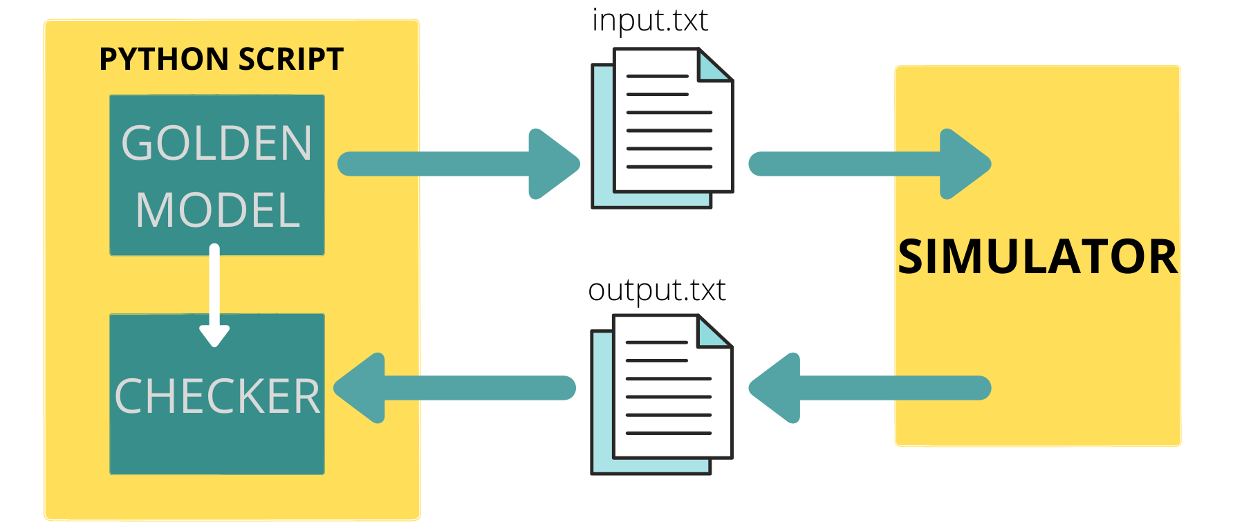
Having looked at all the building blocks, we need to find a way to integrate all of these together. Python to the rescue again. We can use system calls from within python to invoke the simulator of our choice in the command line mode and run the model with inputs taken from the input file that our golden model writes to, finally, the simulator writes the output values to an output file that we read from within our python script and compare the results with the expected values from the golden model.
Let's look at what I mean by that:
N = 16           #Total bitwidth of each number
Q = 12           #Number of bits allotted to represent the fractonal part
I = N-Q-1        #Number of bits allotted to represent the integral part
NoT = 10         #Number of tests to be run

for i in range(NoT):
    a = np.random.uniform(-1,1,1)
    b = np.random.uniform(-1,1,1)
    c = np.random.uniform(-1,1,1)

    p_golden = a[0]*b[0] + c[0]
    p_golden_trunc = truncate(p_golden,2)

    a_fp = float_to_fp(a[0],I,Q)
    b_fp = float_to_fp(b[0],I,Q)
    c_fp = float_to_fp(c[0],I,Q)

    #writing input data to the input.txt file so that the testbench can use them as inputs
    ip_file = open('input.txt','w')
    ip_file.write(format(a_fp)+"\n")
    ip_file.write(format(b_fp)+"\n")
    ip_file.write(format(c_fp)+"\n")
    ip_file.close()
	#invoking the simulator (here icarius verilog) to run our digital design
    #option -D is used to set the values of `define macros, here N and Q
    os.system("iverilog -o mac_manual.vvp -DN=" + str(N) + " -DQ=" + str(Q) + " -DFIXED_POINT mac_manual_tb.v qmult.v qadd.v")
    os.system("vvp mac_manual.vvp ")
	#reading data from the output file that the testbench has written to
    op_file = open('output.txt','r')
    p_practical = op_file.readline()
    #truncating the practical data to two decimal places just like the golden data
    p_practical_trunc = truncate(fp_to_float(p_practical[:-1],I,Q),2)
    op_file.close()

    #as long as both the values differ within a very small threshold, we can say that the verilog         #model is performing fine. This threshold can vary based on your application.
    if(abs(abs(p_golden_trunc) - abs(p_practical_trunc)) < 0.05):
    	print('test_passed')
    else:
    	print('test_failed')
    	print(' a =',a_fp)
    	print(' b =',b_fp)
    	print(' c =',c_fp)
    	print('p_golden =' ,p_golden_trunc)
    	print('p_practical =' ,p_practical_trunc)
    	print(abs(abs(p_golden_trunc) - abs(p_practical_trunc)))
    	break
And here's the testbench that the simulator uses to run the Verilog model:
`timescale 1ns / 1ps
`include "mac_manual.v"
//N represents the total bitwidth
//Q represents the number of bits allotted for the fractional representation
//Both N and Q are passed as compiler directives when the simulator is called
module mac_manual_tb();
    reg clk,rst,ce;
    reg [`N-1:0] a;
    reg [`N-1:0] b;
    reg [`N-1:0] c;
    wire [`N-1:0] p;
    integer ip_file,op_file,r3,r4,r5,r6;

mac_manual #(`N,`Q) a1(clk,rst,ce,a,b,c,p);

initial begin

$dumpfile("mac_manual_tb.vcd");
$dumpvars(0,mac_manual_tb);

a = 0;
b = 0;
clk = 0;
rst = 0;
ce = 0;
#50;

ip_file = $fopen("input.txt","r");
op_file = $fopen("output.txt","w");

rst = 1;

r3 = $fscanf(ip_file,"%b\n",a);
r4 = $fscanf(ip_file,"%b\n",b);
r5 = $fscanf(ip_file,"%b\n",c);
#50;
rst = 0;
ce = 1;
#50;
$fdisplay(op_file,"%b\n",p);

$display("test complete");
$fclose(ip_file);
$fclose(op_file);
$finish();
end
always #10 clk =~clk;
endmodule
Now that we have everything in place, we can run a large number of tests and see if something is wrong with our design, in this case I set the NoT variable to in the script to 5000 and ran the script, it took some time but after around three thousand test cases had passed, it returned one case which wasn't passing. Here's the output it printed...
test complete
test_failed
a = 0000000111100001 = 0.11748478081607838
b = 1111111111111110 = -0.0005302183628016488
c = 1111101101111001 = -0.283025178155329
p_golden = -0.28
p_practical = 7.71
abs_diff = 7.43
After analyzing the internal signals of the module by manually passing just these inputs, I was able to find the error, it was being caused at the following line in the qmult module:
assign quantized_result = f_result[N-2+Q:Q];Basically we're truncating the output of the multiplier to a fixed number of bits so that the data path doesn't become insanely large after each multiplication. But what needs to be observed is that this truncation can cause the loss of really really small numbers, i.e when all the bits in the truncated range are zeros and the non-zero bits lie after that range and hence are not captured in the quantized result.
This is an expected drawback of the lack of precision that a fixed point representation has. It would, though be nice if we had an understanding of how small(/large) the inputs can be for the design to work correctly. To find this out I had to change some lines of the golden model. Currently, I have been using the following lines of code to generate the a,b,c inputs:
    a = np.random.uniform(-1,1,1)
    b = np.random.uniform(-1,1,1)
    c = np.random.uniform(-1,1,1)
This gives random values to a,b,c in the range (-1,1) including those that are really really close to zero, our design seems to be failing. Let's write a function that splits this range and does not assign any value that is too close to zero.
def get_rand():
	e = np.random.randint(0,11)%2
	n = np.random.uniform(-2,-0.005,1)
	p = np.random.uniform(0.005,2,1)
	if(e == 0):
		return n
	else:
		return p
The above function does not return any number that is smaller than 0.005 and greater than zero (similarly, larger than -0.005 and less than zero). 0.005 itself was an arbitrary limit and can be updated by seeing how well the design is performing in this range. The function itself can be written much better and more robust, but it works for the purpose of this test. Let's run it again...
Now it has passed 10,000 tests without failing, which gives me reasonable confidence to assume that the design works for numbers in this range. For this design, if I wish to deal with numbers smaller than 0.005 I can do one of two things:
- Increase the number of bits used to represent the fractional part of the number. But that would reduce the number of bits available to represent the integral part making the largest numbers smaller than the current value 2.
- Increase the total number of bits used to represent the fixed point number (use 32 instead of 16). For example, when I changed N to 32 and Q to 26 I was able to pass 10K tests without needing the use the
get_rand()function. However, the module is theoretically supposed to fail even in that case when two small enough numbers are multiplied. At the end of the day, it's you who have to decide how good is good enough.
Similarly if I wish to deal with numbers larger than 2 (or smaller than -2) without overflowing my design, I'd follow a similar approach and increase the number of bits allotted to represent the integral part.
These are the usual tradeoffs that an engineer faces as a part of the job description and has to make decisions based on the application at hand. Either ways, our quick and dirty automated testbench has helped up discover the problems with the design pretty soon.
In the next article, I explore an even more efficient way to verify designs without having to use HDLs for modelling algorithms. This can be done with Cocotb. You can find that article here
All the code files and testbenches can be found at the Github Repository