
Clock domain crossing (CDC) - The complete reference guide

Now you can access an FPGA LAB environment on demand with chiprentals. This service is currently in the Beta stage and is being provided for free. Go perform your projects in a real world environment. Book your slot here. The PYNQ-Z2 board being offered currently is the best choice for trying out ML and AI acceleration projects as well as traditional FPGA development.
Note: This article can get quite long so use the index to the left for better navigation. If you are instead using this page to choose the best structure for your design situation. You can directly jump to the CDC Decision Tree section for a summary.
Clock Domain Crossing
Clock domain crossing is one of the first few topics that any interviewer will ask you about once the basics are out of the way.
This article aims to be a quick reference guide and an exhaustive checklist for designers to keep coming back to. All the code in this article is also curated in the github repository as a go to library for synchroniser cells.
As a pre-requisite, I believe you should be aware of the basics of static timing analysis (STA) in synchronous digital logic in order to begin appreciating the complexities that arise when an asynchronous clock domain comes into the picture. If you are not accustomed to that already, you should read this article and come back.
Having said that, to give a brief introduction, any design of a reasonable size is going to inevitably have to work with more than one clock frequency. This is because:
- Some operations like CPU processing, math, DSP etc. require as high a clock as you can get.
- Other well established functions like the USB, HDMI, Ethernet etc. have properly defined frequency numbers which need to be honoured if you want to use these functions.
- Then comes other things like the slow SPI, I2C interfaces that cannot go beyond a few megahertz, human interfaces like keyboard, mouse etc that need even less frequencies.
With such diversity on your chip, you cannot afford to run everything at the highest clock in the design. If you did, you’d be wasting too much power and your competitor will put you out of business very soon.
Now, once you have different pieces of your logic working on different clock domains, you need to ensure a reliable transfer of information between these domains, not to mention the completely asynchronous signals coming from outside, like resets, push button signals etc.
The subject of CDC deals with this challenge of reliably doing this transfer while keeping in mind other metrics like latency, power, area etc.
Metastability and it’s impact:
To begin with you need to be clear one what the fundamental problem is in transferring signals across clock domains. If you are not clear about the origins of Metastability and how we measure the reliability of a system (MTBF). Go read this article and come back.
Strategies for good Clock domain Crossing:
Heres a fun doomsday scenario:
Let’s say you use a lot more than two synchronising flops everywhere in your design making your MTBF far far larger than multiple times the lifetime of the universe, but due to all these extra flops explode your area and power numbers so now you have require a slightly more powerful fan unit than the proven one you’ve been using all this while. While your design is flawless, this new fan has a far smaller MTBF and it fails during operation setting off a cascade of failures due to the temperature buildup. What exactly is the MTBF of your system now? 🙂
To prevent such painful scenarios, we need to choose from a variety of possible architectures depending on the nature of the data we’re transferring and it’s criticality.
Possible Issues due to CDC:
I will be listing down the primary issue we need to consider and also giving them a shorthand notation to refer to later when we make a nice table of what circuit solves what problem.
-
Metastability: (MTSB)
At this point I believe you have a good enough understanding of what metastability is and what its impact can be. Just in case you missed the first section of this article. Go read this for a full understanding of metastability.
-
Data Loss: (DL)
The data loss issue, as the name suggests causes some transitions, or data to be lost during the transfer from one clock domain to the other.
This primarily happens when the source domain does not hold the value of the pulse being synchronised for long enough.
Case1 - Metastability:
When the first flop in the synchroniser goes metastable, the metastability can settle in either directions. If it settles in favour of the voltage level that was not the same as the value being transferred by the source, we receive wrong data at the destination.
Case2 - Fast to Slow crossings:
This is simply a blunder where the source domain has a smaller clock period than the destination and data changes to fast before the posedge of the destination domain even sees that change in voltage level.
The Solution:
To prevent data loss the source domain should hold the value for at least one complete posedge of the destination clock.
-
Data Incoherence: (DI)
Data incoherence is simple the problem of data corruption as it traverses domains. If you have a multi-bit signal, like a counter or a state machine state or some other information, you don’t want its value to get modified just because you transferred it to a different clock domain.
Turns out it is very common if you do not take proper care with multi-bit signals.
-
Re-convergence:
This is a more advance version of the Data Incoherence problem that occurs at a slightly more macro level in the design. i.e this issue is visible when you analyse a system where multiple signals are going through a clock domain transfer and then interacting in the destination domain.
Even if you have structurally ensured that metastability does not break your chip, there are things you need to take care of to prevent your design from breaking functionally and this issue is one of them.
Having said that, I would encourage most beginners from skipping this particular topic until they’re comfortable with the rest of the things in this article. The above three issues will keep coming up further but re-convergence is a higher level topic that can be dealt with separately.
Although if you know what you’re doing and would like to dig into the re-convergence problem go read this article.
Since this is a reference guide I’m writing, I will not delve into details and examples of the above issues and rather focus on the different techniques up our sleeves to solve them. In case you need a revision. This article is beautifully written.
Possible design solutions
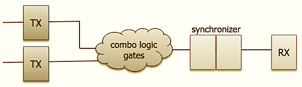
- Multi-Flop Synchroniser
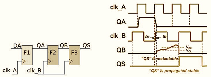
The Multi Flop synchronizer is a very simple and elegant solution that significantly maximizes the MTBF of the crossing. Each flop post the first synchronized output adds an extra full clock cycle to the time available for the metastability to settle. In the article on metastability I have gone a bit deeper into multi-flop synchronisers.
You will see that all the other CDC techniques are clever extensions around this fundamental structure.
Best Practices:
- There should be no combination logic right before the synchroniser flop. Combinational logic, due to having multiple inputs with varying wire lengths, tends to glitch multiple times before it settles to the right value. And glitches can significantly reduce the MTBF of the synchroniser circuit. Hence always flop your design before feeding it to the synchroniser.
- Place the synchroniser flops very close to each other, preferably within the same cell. A more detailed explanation has been given for this in the dedicated article for metastability.
QUIZ YOURSELF-1: Can you explain why a glitch significantly affects the MTBF of the synchroniser circuit? Try to be as precise and articulate as you can. Hint: Have a good look at all the terms in the MTBF equation. You can find it here.
Limitation: - Only useful for single bit data. It's enticing to think that you can just put independent synchronisers for multi-bit data but due to the fact that each flip-flop is slightly different from the rest in its electrical characteristics, one can never ensure that all the synchronisers on this multi-bit bus will settle exactly on the same clock cycle. Hence, you run into the Data Incoherence (DI) problem.
Open Loop
Open loop simple means that there is no feedback to the source domain about whether the data it sent was safely captured on the other side. This might not necessarily be a bad thing if you are sure about the relationship between the clock frequencies and ensure that the source holds the information long enough for it to be safely taken through all the synchronizer stages.
However, in real designs where frequencies keep changing and RTL keeps getting reused, there is a huge risk that due to some change, the pulse might not be wide enough.
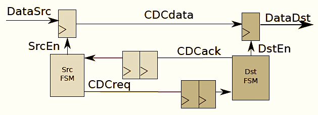
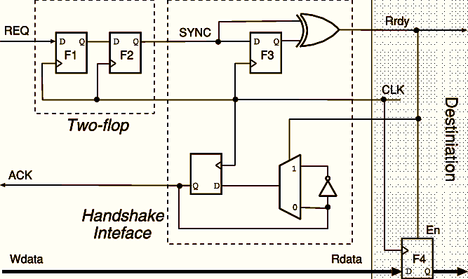
Closed Loop aka Handshaking
In a closed loop system, you set up a protocol that the source shall hold the data stable till it gets an acknowledgement (ack) back from the destination. This is much safer against unwarranted effects due to design changes. The obvious caveat is that your data should be slow enough for the synchronizer to never miss a transaction.
You will often see the word ‘qualifier’ being used to refer to a handshaking signal that ‘qualifies’ the other data bus that’s supposed to be stable during the handshake.
two stage vs four stage handshaking:
The requirement for handshaking brings up more nuanced questions about how exactly the handshaking should be done. This is important because the handshaking method determines the throughput of the channel. Depending on your design this could be an important consideration. Read here about 2 vs 4 phase handshaking.
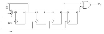
- Toggle synchroniser
For sparse pulses, you’re better off simply toggling a signal on the source side and then using it to manufacture a pulse in the destination. The minor advantage here is that you need not worry about the clock frequencies or the relationship between them chainging in the future and breaking this crossing.
However if you want a measure of exactly how 'sparse' the source pulses should be, you will need to calculate that based on the clock frequencies. Simple rule is that the source data should be stable for as long as it takes to safely take it through the synchroniser stages at destination.
- Mux-recirculation:
This technique simplifies the CDC circuit for a multi-bit bus in specific cases where the data is not fast moving. This is also called the MCP or multi-cycle path strategy in some literature. A qualifier pulse is transferred to the destination domain using a double flop synchroniser or a toggle synchroniser and this pulse in the destination domain enables the sampling of the multi-bit bus. By protocol, data on the multi-bit bus is ensured to be stable until the qualifier pulse reaches the destination domain. This technique is an example of how a little bit of cleverness can significantly reduce the resources required in a design while ensuring safety. Limitation: Data on the bus is not allowed to change on every cycle. There has to be a guarantee that it shall remain stable for the amount of time it takes for the qualifier to reach the destination domain (which depends on the exact values of the clock frequencies).
Handshaking is often added to this structure to make it more robust. The considerations for the type of handshaking mentioned above apply here too.
- AFIFO
The asynchronous FIFO is arguably the most clever way to come up with a robust system that can ensure safety in all kinds of designs. It might look like the ultimate solution for any situation and most people, especially in FPGA tasks, where the rigour to make the most efficient design lower, use this block for almost any kind of CDC.
Now that might be a safe way to do things but AFIFOs can be resource intensive and have to be written with outmost care given the amount of blind reliance on them.
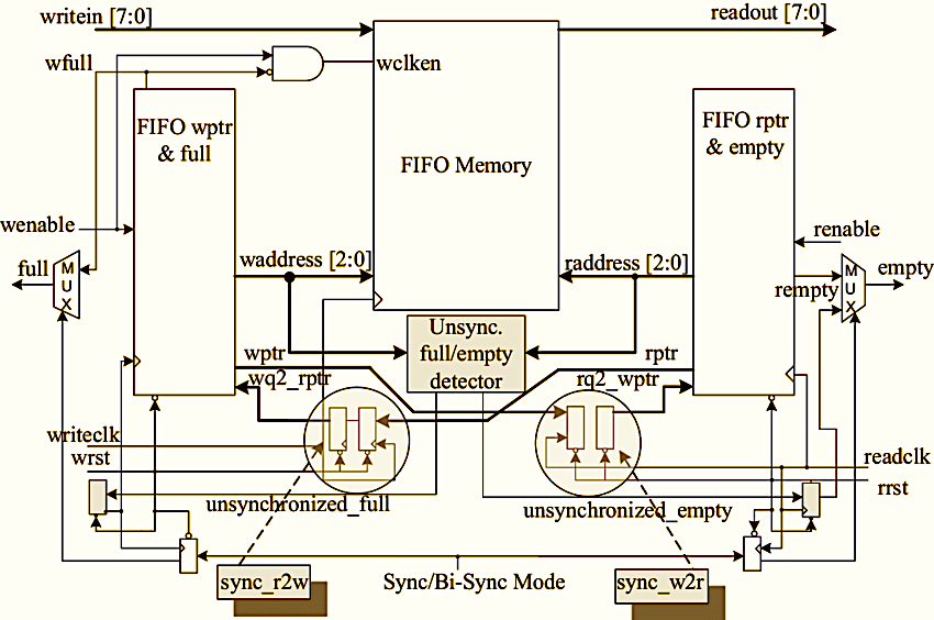
The AFIFO uses a memory along with read and write pointers to safely transfer data. The source writes to this memory and destination reads from it.
Complexity arises in managing this process, i.e ensuring there is no collision between the read and write, the memory does not overflow or underflow, or the source does not overwrite what’s already written.
For all this, an AFIFO maintains pointers. The challenge is in transferring the value of these pointers from one domain to another for generating these control signals.
Remember, these are multi-bit dynamically changing data values. So far in our journey, we haven’t come across a simple circuit that can safely transfer these values.
Data Incoherence (DI) is the primary issue we haven’t solved for this particular scenario.
Now comes the most clever part, Gray code is an encoding technique that has some interesting properties. From one value to the next, only one bit changes in the Gray code while all others remain stable. Hence making it a single bit pulse problem.
If you can ensure that the pointers only move from on value to +1 or -1 of that value, you have reduced the complex issue to an already solved one. That to me is pure genius.
QUIZ YOURSELF-2: Let's say you have a multi-bit counter that you wish to do CDC for. You convert this counter from bniary into gray coding. Additionally, the value of this counter changes once in 500 clock cycles. Can you safely transport this counter to the other domain using an independent multi-flop synchronizer for each bit of the gray code?
I won’t go into the exact details of the AFIFO and it’s RTL nuances. People far smarter than me have done it very well. Here is a collection of resources on this topic.
| Name | link | Description |
|---|---|---|
| ZipCpu article on AFIFO | link | My go to article every time I revise this concept |
| ZipCpu tutorial paper on AFIFO | link | A more detailed version where he talks about the various issues and how to catch them in verification |
| Sunburst Paper by Clifford Cummings | link | Internet’s oldest and most popular paper on this topic |
| A critique of the above paper | link | JL Gray contesting some of the aspects of the above Cummings paper |
QUIZ YOURSELF-3: Your design has a 64-bit datapath and you need to perform CDC on it. In your library, you only have AFIFOs 32-bit width. You take two of these and connect them side by side to make one 64-bit FIFO. All the other signals like the write enable and read enable are connected parallel to both the FIFOs. To make life easier, the design is such that you don’t really need to worry about the FIFOs overflowing or underflowing.
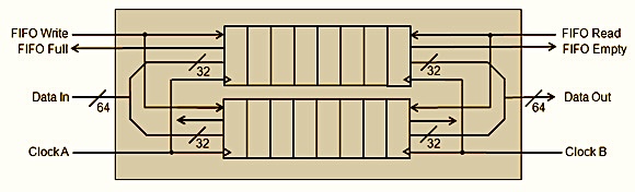
Will this design work correctly or will it fail at some point. if there is going to be a failure, what will it look like?
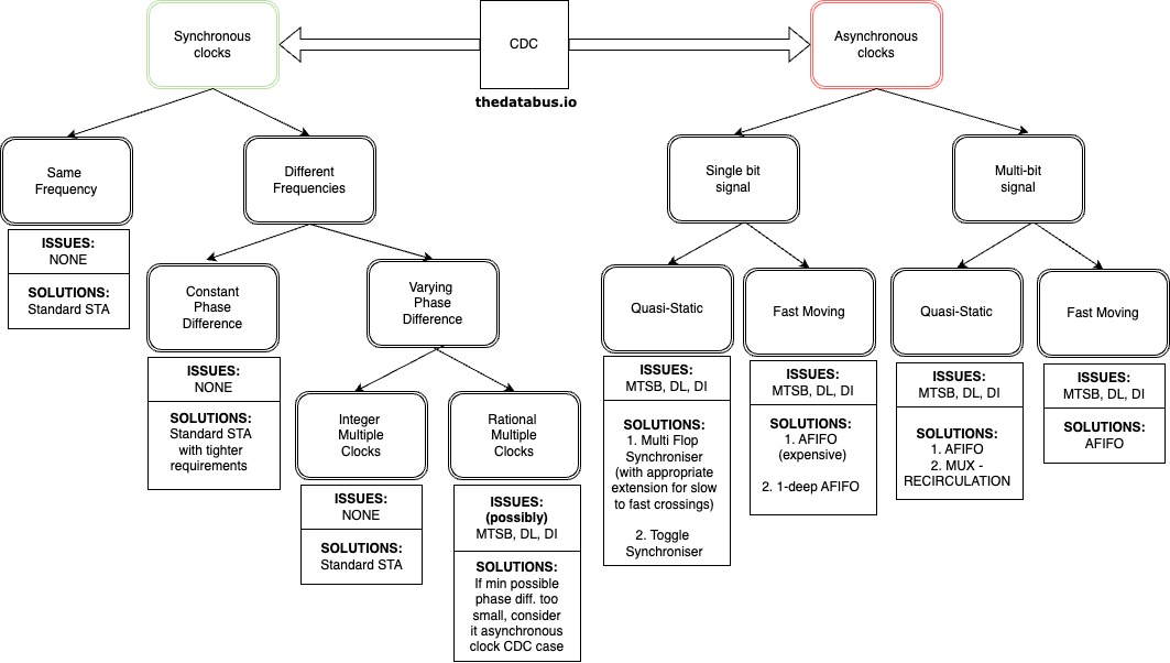
CDC Decision Tree
Take a good hard look at this diagram
Open Source CDC code
Given the variety of these above structures already available out there, let me make a list of the good ones related to what we have discussed abvoe.
| Link | Description |
|---|---|
| link | - Toggle Synchroniser |
| link | - Handshake Synchroniser |
| link | - Mux Recirculation |
| link | - A simple, verified AFIFO based on Cummings papers |
| link | - AXI compliant AFIFO |
Interesting Cases
In the Decision tree, if you are a keen observer you will find two specific cases particularly interesting.
- Crossing between two Synchoronous clocks with varying phase difference and the clock frequencies are not integer multiples.
- This is interesting because despite the face that the two clocks here are generated from the same source, purely due to their time period durations, the relative phase between them constantly keeps changing. The designer needs to detect this before hand and decide on whether or not this crossing requires the treatment of a typical Asynchonous crossing.
- For that, we need the value of the minimum phase possible between these two clocks. And if this value is far less than the time period of both the clocks, there is a good chance the timing tools will not have enough slack to fit the combinational logic within this phase duration. The designer now has to take a call what kind of crossing circuitry is needed.
- To take this call, you might have to use the following simple algorithm to find the smallest phase difference between the two clocks:
- If the time periods are coprimes (meaning no other common divisors other than 1). Their LCM is simply their product.
- After the LCM, the same pattern repeats.
- So, list out the timestamps of the posedges of these clocks till their LCM and then find out the point of minimum distance between the posedges.
- The case where you need to transfer a single pulse across domains with the condition that this is a frequently changing pulse and not Quasi-static.
- From our analysis so far it is clear that for data of this nature an AFIFO is the only solution.
- But an AFIFO for a single pulse seems like a huge waste of resources. Can we do better?
- I was once asked this question in an interview, so I felt I should present the solution in the same format. Read it here
How to verify CDC safety in your design:
In a real industry setting, the general rule is that if something hasn’t been tested, then it doesn’t work.
To check design functionality there are a variety of techniques available. The question is how to check for correct CDC.
QUIZ YOURSELF-4: If you were building a simulation model of some design that had CDC, how would you approach the CDC related circuitry? Is it possible to simulate all aspects of this circuit?
To solve this, we use tools like Spyglass from synopsys to look at our code, detect clock domain crossings and also guess what kind of structures we’ve used to ensure safe crossing. Even among the tools, there are two types of checks you can perform.
Structural vs Functional checks
- Structural checks: In this, the tool simple detects blocks of code where CDC occurs and tries to infer if a valid and well known synchronisation technique is being used to perform this crossing. The tools have a long list of popularly used synchroniser blocks. If it fails to find any, it will complain.
- Functional checks: These are more rigorous checks that simulate worst case scenarios to test for the robustness of a CDC scheme that has been used (and has already satisfied a structural CDC check requirement).
For example, if you are transferring a signal between two domains with the same clock period but asynchronous to each other, there could be situations where due to clock Jitter and similar causes, the period of one clock becomes slightly smaller than the other or one clock goes out of phase with the other.
In each of these situations your CDC circuit might behave differently and hence break.
The tool uses formal methods to create these worst case scenarios and find the possibility of a breakage. Often, any issue here leads to the Data Loss problem showing up.
QUIZ YOURSELF-5: Is metastability a structural issue or a functional issue?
NOTE: Formal methods are something I hope to master enough to write about some day. To explain simply, formal tools use advanced math to convert your circuit into a huge state machine. In this state machine there would be some states that signify undesired behaviour by your actual circuit. If the tool can cleverly find a logical path to reach any of those states, it has essentially found a bug in your design.
In a real job, tasks related to CDC might look something like this:
- Your company has a library of synchronisers and related circuits that have been historically used and optimised according to the nuances of the toolset used by your team.
- You are expected to use these blocks whenever you need to perform CDC. The real challenge is to use the above mental models to decide on which exact block to use and justify it.
- At some stage, you run tools like Spyglass over your code which analyse these structures and give you feedback on their efficacy and completeness. The designer is expected to look at these reports and address any concerns the tool might have raised. Often the tool takes a very rigorous approach and generates several warnings mainly because it does not have the intelligence to understand the intent of your design. The designer’s job in this case is to waive off these warnings after taking a good look at them and addressing the concern being expressed. For a design to be considered mature, there should be no warnings left.
- If you’re curious what the exact mechanics of applying these tools looks like. I found this document by Synopsys floating around.
Synchronising resets and IOs:
Reset Synchronisation: Read this
Quiz Questions Answers:
- Can you explain why a glitch significantly affects the MTBF of the synchroniser circuit? Try to be as precise and articulate as you can. Ans. A glitch is a fast changing pulse that can occur anywhere irrespective of the clock edge due to varying delays through combinational gates. Thanks to the super quick transitions that a glitch causes, the term Fd in the denominator of the MTBF equation, which is a number ‘equivalent’ to the frequency of the data skyrockets in the presence of a glitch. Thus significantly reducing the MTBF.
- Let's say you have a multi-bit counter that you wish to do CDC for. You convert this counter from bniary into gray coding. Additionally, the value of this counter changes once in 500 clock cycles. Can you safely transport this counter to the other domain using an independent multi-flop synchronizer for each bit of the gray code? Ans. No. Just because your data is gray code does not mean that you can do a multi-bit cdc with simple synchronisers. The fundamental requirement here is that only one bit should change at a time while all others remain stable. For this to happen you need an incrementing or decrementing counter like structure thats used in AFIFOs.
- Two 32 bit FIFOs connected side by side to make one 64-bit FIFO. will this design work correctly or will it fail at some point. if there is going to be a failure, what will it look like? Ans.Think hard about it and when you want to check the answer read this.
- If you were building a simulation model of some design that had CDC, how would you approach the CDC related circuitry? Is it possible to simulate all aspects of this circuit?* Ans. You can only simulate the functional aspect of a synchronizer circuit using a random number picker to randomize the delay through the circuit based on how many flops there are. But it is not possible to simulate Metastability. It is a structural issue only possible in hardware due to underlying analog components.
- Is metastability a structural issue or a functional issue? Ans. Metastability is a structural issue. It can lead to further functional issues due to the uncertainty/variability it introduces in the circuit but metastability itself is a structural problem that can directly cause harm to the actual chip.
Resources:
Apart from the plethora of papers already linked throughout the article. Here are a few great ones:
- link -> One of the golden references for CDC
All the files can be found at the Github Repository